Flexi-TEER
Assembly Instructions
Step 1: Order PCB
- Download the Gerber File, BOM and Pick and Place File for the PCB.
- Sign into account or create an account if new.
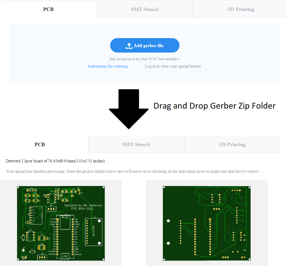
- Go to JLCPCB Website website and upload Gerber zip folder.
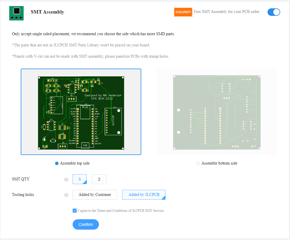
- While on the page, drag and drop Gerber zip folder into area that asks for it. In the example image, I also used the SMT assembly service by selecting it.
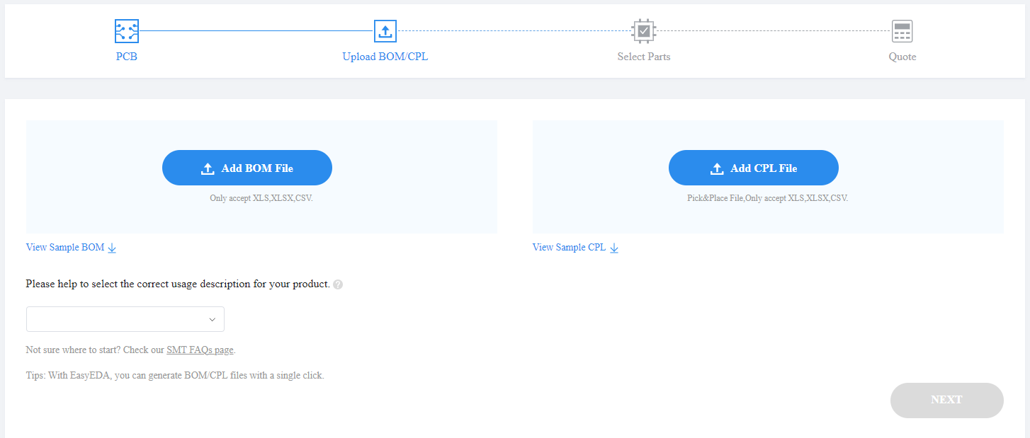
- Upload BOM and Pick and Place .csv files. Select electronics and hobbies/developmental board for the description.
- Select parts that you desire to be soldered onto the board for you via the SMT assembly service.
i Note i SMT Assembly service is an affordable service where certain components are soldered to the board for you. Not every current component is compatible with this service. I recommend using this as its time consuming to solder these very tiny components.
Step 2: Order Components
- Go to mouser project and order integrated circuit (IC) components.
- Order remaining generic parts such as 603 footprint resistors and capacitors.
i Note i If you used the SMT assembly service, you do not need to order those parts again.
i Note i Not all parts make sense to order individually. I recommend ordering the 603 footprint resistors and capacitors as part of variety book set.
Step 3: Solder Surface Mount Components (SMD)
Solder components onto circuit board in the order below with a Soldering Iron{Qty:1, cat: tool}. A strategy that has worked well with small chips is to use a soldering iron with very fine 0.3mm solder. First place some solder onto each pad for the component, then place component with Grabber Tool{Qty:1, cat: tool} and press into place with tweezers and gently touch each lead from the component with the soldering iron until the solder melts around it.
i Note i a Curved Soldering Iron Tip{Qty: 1, cat: tool} will help solder SMD components to board.
i Note i If you used the SMT service, some of these parts may already be installed.
- 10uF SMD Capacitor{Qty: 2}
- 35pF SMD Capacitor{Qty: 2}
- 0.1uF SMD Capacitor{Qty: 2}
- 2k SMD Resistor{Qty: 2}
- 50 SMD Resistor{Qty: 1}
- 300 SMD Resistor{Qty: 3}
- 1k SMD Resistor{Qty: 1}
- SPDT Switch{Qty: 6}
- INA592 Diff Amp{Qty: 1}
- REF200 Current Source{Qty: 1}
- LM358 OP Amp{Qty: 1}
Step 4: Solder Through Hole Components
i Note i a Straight Soldering Iron Tip{Qty: 1, Cat: tool} will help solder through hole components to board.
- 2x 16x1 Female Pin Header{Qty: 2}, one for each side of Arduino Nano IOT
- 1x 7x1 Female Pin Header{Qty: 1} in ad9833 socket
- 1x 10x1 Female Pin Header{Qty: 1} in ADS1115 socket
Step 4: Solder Male Pin Headers
If ordered any breakout boards (ADS1115, AD9833, Arduino, etc.), solder male pin headers to each board.
Step 5: Attach Breakout Boards
Attach each breakout board and Arduino into respective sockets.
Step 6: Flash Arduino Sketch
Currently no sketch is available.